The FR-4 material properties that matter most depend on what your PCB must withstand: electrical signals, assembly heat, operating temperatures, voltage stress, moisture, and mechanical loading. Start with dielectric constant and loss, thermal expansion and stability, insulation performance, and mechanical requirements.
FR-4 is a flame-retardant, glass-reinforced epoxy material class. It does not identify one fixed formulation or set of numerical properties. Select a named laminate and evaluate its data under conditions relevant to your design.
This guide explains how to interpret those properties, compare candidate constructions, and give your PCB supplier requirements that engineering and purchasing can both use.
Key Takeaways
- Record the laminate product, construction, frequency, temperature, and test method behind important values.
- Evaluate Tg alongside decomposition, expansion, delamination, and long-term thermal data.
- Use construction-specific electrical data when developing a stackup; a generic FR-4 Dk is insufficient for release.
- Define acceptance requirements and substitution approval before ordering.
FR-4 Material Properties at a Glance
A Reference Table With Values, Units, and Test Conditions
The examples below are published typical values for Isola 370HR, not universal FR-4 limits or guaranteed purchase specifications. Methods are reproduced as identified in its 370HR datasheet.
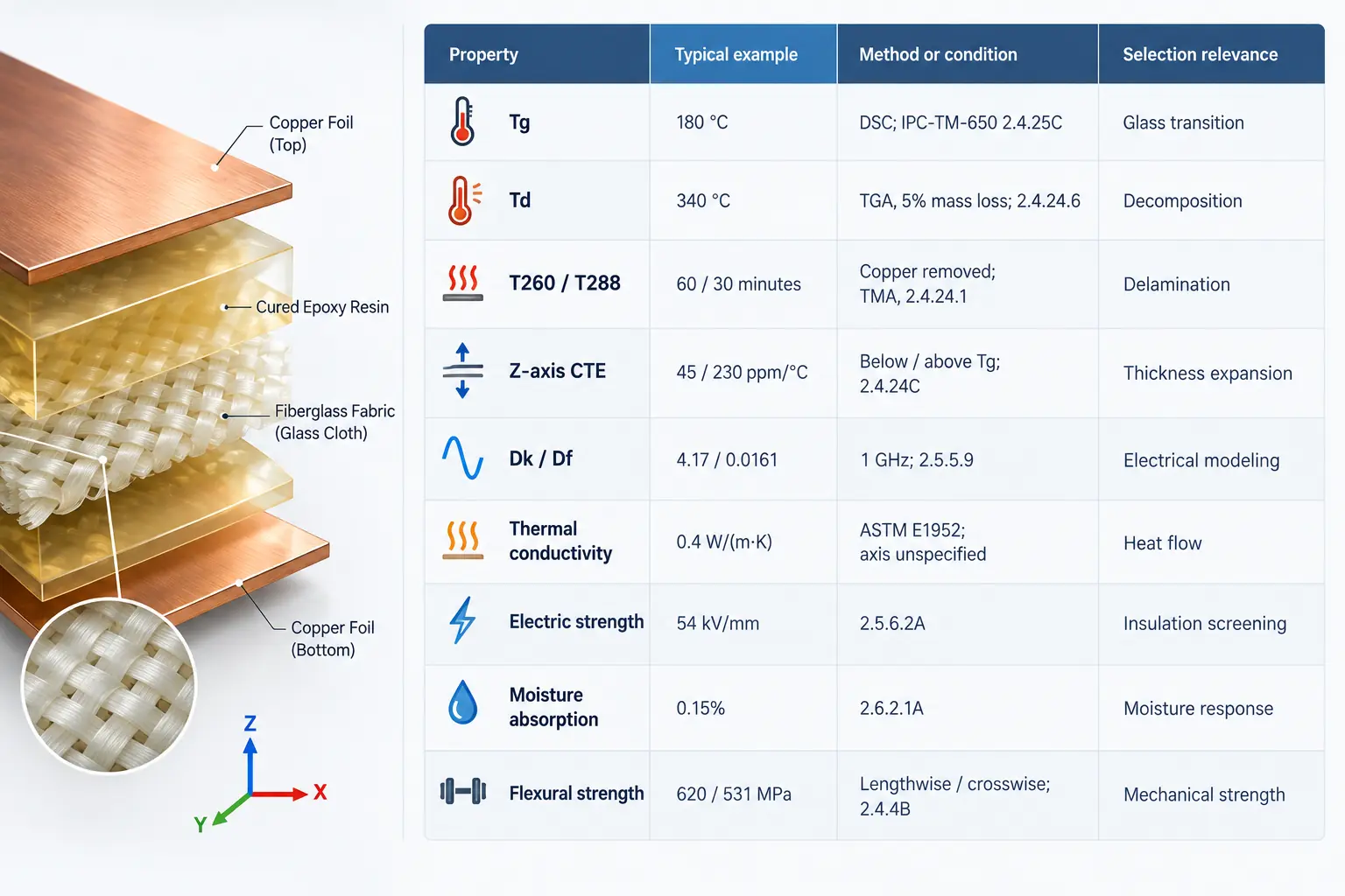
| Property | Typical example | Method or condition | Selection relevance |
|---|---|---|---|
| Tg | 180°C | DSC; IPC-TM-650 2.4.25C | Glass transition |
| Td | 340°C | TGA, 5% mass loss; 2.4.24.6 | Decomposition |
| T260 / T288 | 60 / 30 minutes | Copper removed; TMA, 2.4.24.1 | Delamination |
| Z-axis CTE | 45 / 230 ppm/°C | Below / above Tg; 2.4.24C | Thickness expansion |
| Dk / Df | 4.17 / 0.0161 | 1 GHz; 2.5.5.9 | Electrical modeling |
| Thermal conductivity | 0.4 W/(m·K) | ASTM E1952; axis unspecified | Heat flow |
| Electric strength | 54 kV/mm | 2.5.6.2A | Insulation screening |
| Moisture absorption | 0.15% | 2.6.2.1A | Moisture response |
| Flexural strength | 620 / 531 MPa | Lengthwise / crosswise; 2.4.4B | Mechanical strength |
Dk and Df are dimensionless. A value without an identified direction should not be assigned to every axis in a simulation.
Typical Datasheet Values vs. Purchase Requirements
A typical value describes reported material performance. A purchase requirement defines what must be accepted or rejected.
For critical properties, agree on the limit, method, conditioning, and required evidence. Ask whether compliance is demonstrated through material qualification, a certificate, or specified testing. Do not assume every datasheet property is measured on every delivered PCB.
Likewise, do not turn a typical value into a minimum simply by copying it into a drawing. Confirm that the supplier can support the proposed acceptance requirement.
Why FR-4 Does Not Have One Fixed Set of Properties
Resin Systems, Glass Reinforcement, Core, and Prepreg
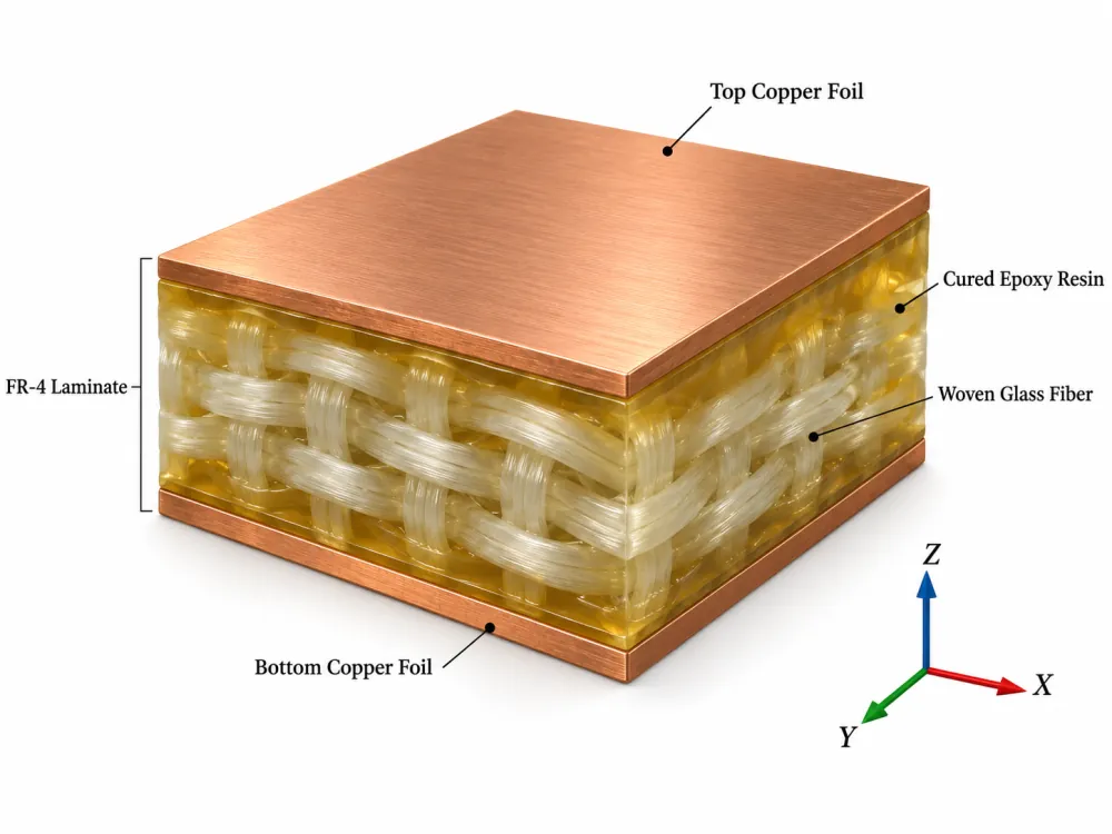
FR-4 combines woven glass reinforcement with an epoxy-based resin system. The resin formulation, glass style, and resin-to-glass proportion affect the resulting material. Copper foil is a separate part of the copper-clad construction.
In multilayer fabrication, a core is a cured laminate, commonly supplied with copper cladding. Prepreg contains partially cured resin and reinforcement; it bonds layers during lamination. Specify the finished dielectric construction needed by the design, rather than treating an uncured prepreg sheet as a finished layer.
Isola’s material-selection guidance identifies resin, reinforcement, and copper-foil characteristics as contributors to electrical performance. A laminate choice therefore needs to be considered together with its stackup. Isola material-selection guidance.
Material Designations, IPC Specifications, and UL Ratings
These labels answer different questions:
- FR-4: Identifies the material class.
- Manufacturer and product designation: Identify the particular laminate system.
- IPC-4101 specification sheet: Identifies applicable base-material requirements when specified.
- UL 94 rating: Describes performance in a flammability test.
IPC-4101 addresses base materials for rigid and multilayer printed boards, including construction and property requirements. Specify the applicable revision and specification sheet when required by the project. IPC-4101 scope and contents.
Verify the required flammability rating for the selected material and construction. A flammability classification does not establish a continuous operating temperature; UL treats flammability and long-term thermal evaluation separately. UL materials testing.
Electrical Properties: Dk, Df, and Insulation Performance
Choosing Dk and Df Data for Your Frequency and Stackup
Dielectric constant, or relative permittivity, influences capacitance, propagation delay, and transmission-line impedance. Dissipation factor, also called loss tangent, describes dielectric loss.
For material comparison, match the frequency, test method, and construction. For design, ask which Dk/Df data or model the supplier recommends over the relevant frequency range.
A transmission line’s effective permittivity depends on where its fields travel. For example, a surface microstrip’s fields occupy both the substrate and the region above it. Its model must account for geometry as well as bulk laminate Dk.
Df alone cannot predict total channel loss. Conductor loss, copper roughness, and impedance discontinuities also contribute. Consequently, there is no useful universal frequency at which every FR-4 construction becomes unsuitable. Evaluate the channel length and loss budget. Isola transmission-line and loss analysis.
Before routing critical nets, agree on the construction, finished dielectric thicknesses, copper, electrical model, and impedance targets. See the controlled impedance PCB design guide for the wider stackup workflow.
Dielectric Strength, Resistivity, and CTI
These properties describe different insulation behaviors:
- Dielectric strength: Breakdown voltage per unit thickness under specified test conditions.
- Volume and surface resistivity: Resistance to conduction through the material or along its surface.
- Comparative tracking index, or CTI: Relative resistance to forming conductive tracks across an insulating surface under the test conditions.
IPC provides separate methods for electric strength and volume/surface resistivity. UL describes CTI as a separate assessment of tracking resistance.
Do not multiply a datasheet breakdown value by board thickness and treat the result as an approved working voltage. Establish insulation requirements at the product level, including the applicable spacing, environmental, and verification requirements.
Thermal Properties: Tg, Td, Expansion, and Heat Flow
Tg, Decomposition, Delamination Time, and Long-Term Temperature Ratings
Tg describes the glass-transition region, where the resin’s stiffness and expansion behavior change. It is neither a melting point nor a complete service-temperature rating. DSC measures the transition through heat-capacity behavior, while TMA examines dimensional response. Preserve the method when comparing results. IPC DSC method, IPC TMA method.
Td concerns thermal decomposition. The mass-loss criterion matters: IPC’s TGA method reports temperatures at both 2% and 5% loss. Comparing one material’s 2% value with another’s 5% value can mislead. IPC decomposition-temperature method.
T260 and T288 describe time to delamination at the specified test temperature. Specimen preparation and copper condition matter. These measurements do not state how many reflow passes a finished assembly can tolerate. IPC time-to-delamination method.
Relative thermal index, or RTI, addresses long-term thermal aging. It should be considered within its recognition conditions and the complete product evaluation. UL’s thermal-aging work is distinct from short-term thermal characterization. UL thermal evaluation.
The practical task is to review the expected service temperature, soldering profile, rework exposure, and reliability requirements together. A high Tg value alone cannot settle that review.
X/Y and Z-Axis CTE Below and Above Tg
The coefficient of thermal expansion describes dimensional change with temperature. X and Y lie in the board plane; Z runs through its thickness.
Ask for the direction and temperature interval behind each CTE value. A below-Tg coefficient cannot represent an entire excursion that crosses the transition. Also distinguish a coefficient in ppm/°C from total expansion expressed as a percentage over a stated interval. IPC thermal-expansion method.
For via reliability review, include the laminate’s thickness expansion alongside board thickness, hole geometry, plating, and the expected thermal cycles. CTE is one input to that assessment, not a stand-alone reliability guarantee.
Thermal Conductivity and the Complete Board Heat Path
Thermal conductivity describes heat transport. It answers a different question from whether a resin tolerates a thermal exposure.
When a component runs too hot, review its entire cooling path: attachment to the board, copper spreading, thermal vias, interfaces, airflow, and any heat sink. Increasing Tg alone does not establish an improvement in heat removal.
For simulation, use direction-appropriate material data and represent copper separately. Avoid applying one laminate conductivity value to a finished multilayer board containing patterned copper and vias.
Mechanical Properties and Moisture: What Else to Check
For mechanically loaded boards, distinguish strength from stiffness. Strength concerns failure under load; modulus describes resistance to deformation. Board thickness, support locations, and mounting loads must also enter the mechanical assessment.
Preserve the test direction when comparing reinforced laminates. IPC’s flexural-strength method explicitly calls for lengthwise and crosswise specimens. Copper adhesion should be reviewed separately when processing or rework stresses matter. IPC flexural-strength method.
Moisture absorption is also method-dependent. The water-absorption method referenced in the example table measures mass gain after conditioning and a specified 24-hour immersion. That result does not describe every humidity exposure or prove the electrical reliability of a finished board. IPC water-absorption method.
For humid, electrically biased applications, request relevant insulation-reliability evidence in addition to absorption data. Confirm storage and pre-assembly handling requirements with the fabricator.
Worked Example: Reading an FR-4 Datasheet
Identify the Product, Revision, Construction, and Test Conditions
Hypothetical scenario: A team is developing a six-layer controller with controlled-impedance signals. Two proposed core constructions have the same laminate product name and nominal thickness. Purchasing asks whether they are interchangeable.
The engineer records the document revisions: the 370HR product datasheet identifies revision E, while the separate construction tables identify revision C, dated March 16, 2020. Each numerical value stays attached to its own source.
At a shared 1 GHz comparison point, the construction tables report:
| 370HR core construction | Resin content | Nominal thickness | Dk | Df |
|---|---|---|---|---|
| 1 × 2116 glass | 47% | 0.102 mm | 4.26 | 0.018 |
| 1 × 10⁶ + 1 × 1080 glass | 60% | 0.102 mm | 4.00 | 0.021 |
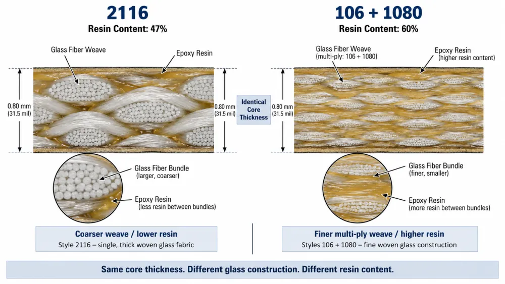
These are published reference data, not acceptance limits. The standalone table does not identify a test method for these entries. Isola 370HR construction tables.
Decide Which Values Can Be Compared or Used in the Design
The comparison shows that matching product name and nominal thickness does not establish identical electrical behavior.
The engineering response is to:
- Confirm which construction is actually proposed and obtain the applicable current data.
- Agree on the model and finished dimensions with the fabricator.
- Recalculate impedance and channel performance before approving the change.
- Record the approved construction and substitution conditions.
Neither the product-level table nor this comparison provides enough information to predict the finished impedance by itself. The example also does not demonstrate that one construction is universally better: the selection depends on the circuit and stackup.
How to Select a Laminate and Review an Alternative
Start with the limiting design requirement. The following table is a practical review framework, rather than a universal material recommendation.
| Main concern | Evidence to request | Decision to make |
|---|---|---|
| Impedance or propagation delay | Construction-specific Dk model and finished stackup | Confirm trace geometry and tolerances |
| Channel loss | Df across the relevant band, copper profile, channel analysis | Keep the proposed laminate or evaluate lower-loss options |
| Assembly and thermal cycling | Tg method, Td criterion, expansion, delamination data, relevant qualification | Confirm suitability for the intended thermal exposures |
| Heat removal | Directional conductivity and complete thermal model | Improve the heat path or evaluate another construction |
| Insulation and humidity | Required electrical properties and relevant environmental evidence | Confirm product-level insulation requirements |
| Cost and supply continuity | Proposed material, construction availability, lead time, alternate documentation | Approve a documented sourcing strategy |
For broader alternatives, consult the PCB material selection guide .
When reviewing a substitute, separate matching a specification from preserving a validated design. Meeting the same minimum requirement does not establish identical electrical behavior or fabrication response.
Request a comparison against the properties that matter to your board. Document changes in construction, copper, methods, and recognition status where relevant, then decide whether analysis or qualification must be repeated. Purchasing should receive a clear disposition: approved, approved with conditions, or rejected.
What to Include in Your FR-4 PCB Inquiry
An effective inquiry combines fabrication files with the operating requirements those files cannot communicate.
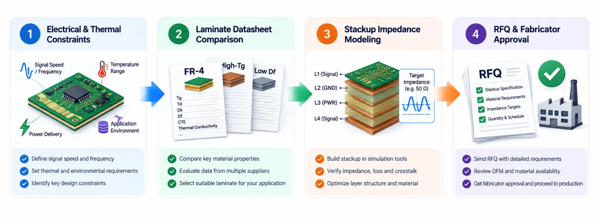
- Application and environment: Function, expected board temperatures, humidity, voltage stress, and service-life expectations.
- Assembly exposure: Planned soldering processes, available profiles, and anticipated rework.
- Board construction: Layer count, finished thickness and tolerance, copper requirements, and proposed stackup.
- Electrical targets: Impedance values and tolerances, relevant frequency range, critical channel lengths, and loss or delay limits.
- Material requirements: Mandatory manufacturer/product, applicable specification and revision, or measurable performance criteria where material choice is open.
- Acceptance and documentation: Required property limits, methods, conditioning, certificates, traceability, and any agreed test reports.
- Substitution policy: Whether alternatives are allowed and who must approve them.
- Commercial requirements: Prototype and production quantities, delivery target, and continuity needs.
Where the exact material is still undecided, ask the supplier to identify the proposed laminate and construction and explain how they address the stated requirements.
For performance-sensitive work, useful inquiry wording is:
Please identify the proposed laminate manufacturer, product, core and prepreg constructions, and supporting datasheet revisions. State any departures from the supplied requirements. Obtain written engineering approval before changing the approved material or construction.
The goal is an agreed material specification connected to the actual PCB design. Send your stackup, fabrication files, and operating requirements with your FR-4 PCB inquiry to LEADHUI PCB.