Surface-mount components attach to pads on a circuit board’s surface. Through-hole components have leads that pass into holes in the board for soldering. Surface-mount technology (SMT) often suits compact layouts and automated assembly; through-hole technology (THT) can be useful when a selected component or its mechanical load calls for it. Many boards use both.
The right choice depends on the parts, the forces they encounter, the board layout and the production plan. This comparison takes those decisions one at a time, then follows a fictional mixed-technology board through assembly and an illustrative cost calculation.
Key Takeaways
- Surface-mount devices attach at surface pads; through-hole component leads pass through board holes.
- SMT generally offers more layout density and supports automated placement. Through-hole leads can provide an additional load path, but neither method guarantees joint reliability.
- A mixed board can use SMT for compact parts and through-hole parts where the actual component and load requirements justify them.
- Compare setup, component, fabrication and assembly costs at the intended quantities. A crossover calculated for one set of assumptions is not a universal threshold.
Surface mount vs through hole: key differences
| Consideration | Surface mount | Through hole |
|---|---|---|
| Attachment | Terminations solder to pads on the board surface. | Leads enter holes and are soldered to the board. |
| Space and routing | Small packages and placement on either side can support dense layouts. | Component holes occupy board area and may restrict routing through other layers. |
| Typical assembly | Paste, automated placement and reflow are common. | Insertion followed by hand, wave or selective soldering is common. |
| Mechanical load | Check joint loading, retention features and any enclosure support. | Leads and plated holes can help carry loads; support and testing still matter. |
| Rework | Small or hidden joints may need specialized tools. | Accessible leads can be convenient to hand solder, but multi-pin parts can be difficult to remove. |
| Cost drivers | Parts, stencil and machine setup, placement, reflow and inspection. | Parts, drilling and any insertion, soldering, fixture and inspection steps. |
These are design tendencies, not ratings for every package. Texas Instruments’ overview of voltage-regulator packaging notes, for example, that through-hole leads can obstruct traces on underlying layers. The actual restriction depends on the board and the part.
What are SMT, SMD and through-hole technology?
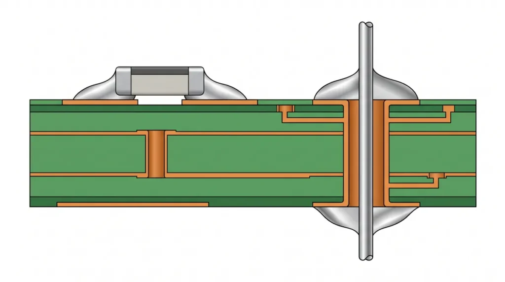
Surface-mount technology is a method of attaching components to conductive pads on the PCB surface. A surface-mount device, or SMD, is a component designed for that method. An SMD may have visible leads, end terminations or contacts underneath its body. The surface-mount technology guide explains common packages and assembly stages.
Through-hole technology uses component leads inserted into board holes. For electrical connections, the holes are commonly plated: copper coats the hole wall and connects it to the required pads or layers. A non-plated hole has no conductive wall and commonly serves a mechanical purpose. See the through-hole PCB design guide for hole types and layout considerations.
The cover illustration shows simplified cross-sections; neither drawing is to scale. A design can combine both mounting methods on the same PCB.
Design and reliability trade-offs
Board space and routing
SMT offers many small packages and allows suitable components on either face of a board. That flexibility can help a dense design, although each package needs its own pad pattern, clearance and access for assembly or rework.
A through-hole lead takes up a hole and the associated clearance. A hole through a multilayer board can also interrupt routing on layers between its entry and exit. Compare the actual component footprints and the fabricator’s design rules: a particular SMD is not automatically smaller than every through-hole alternative.
Mechanical stress and electrical performance
For a connector that users plug and unplug, trace the force from the mating interface into the connector, solder joints, board and enclosure. Through-hole leads can contribute to mechanical retention. Some surface-mount connectors also have retention features or can be supported by fasteners or the enclosure.
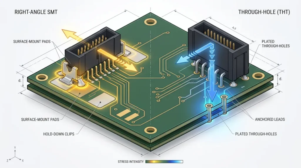
Samtec’s guidance on connector lock clips discusses added retention and the strain repeated mating can place on joints. Check the selected part’s drawing, load ratings and intended tests; a mounting style alone does not establish reliability under vibration or repeated use.
The same care applies to heat and electrical limits. Use each part’s current, voltage and temperature ratings and the board’s thermal design. Texas Instruments notes that a suitable PCB layout can give some surface-mount packages thermal resistance comparable to certain through-hole packages. Neither mounting method is inherently the high-power choice.
Prototyping, rework and part availability
A large through-hole part with accessible leads may be straightforward to fit by hand. Removing a connector with many soldered pins from a plated multilayer board can be harder. SMT rework ranges from simple hand soldering of accessible parts to work that needs magnification, controlled hot air or other equipment for small or concealed joints.
Check availability before committing to a footprint. A needed IC, connector or replacement part may be offered in only one package, and an apparently similar package may have a different pinout or rating.
How to choose for a mixed-technology board
Consider a fictional controller board with one surface-mount IC, imperial 0603-size surface-mount resistors and a four-contact connector that will be plugged and unplugged. Two candidate layouts keep the IC and resistors unchanged:
- SMT option: a four-contact surface-mount connector without through-hole mounting tabs.
- Mixed option: a four-contact through-hole connector on the same SMT board.
The example assumes suitable candidates might exist. It does not establish that any two real connectors are interchangeable. Confirm their pinouts, ratings, dimensions and mating parts before comparing them.
| Requirement | SMT candidate | Mixed candidate | Check before selection |
|---|---|---|---|
| Electrical and fit | Surface-pad footprint. | Lead and hole footprint. | Pinout, voltage and current ratings, mating part and enclosure clearance. |
| Mating load | Assess joint and enclosure support. | Assess lead, barrel and board loading. | Insertion force, retention features, mating cycles and required tests. |
| Layout | Reserve pads and rework access. | Reserve plated holes and routing clearance. | Manufacturer drawings, board rules and access for the chosen process. |
| Production | Check connector placement and reflow compatibility. | Plan insertion and a suitable soldering operation. | Assembler review, inspection access, parts supply and quote assumptions. |
If the SMT connector meets the load requirements with the available support and passes the agreed tests, it may be the simpler route for this board. If the through-hole candidate better meets the verified mechanical or component requirements, the added operation may be worthwhile. Ask the assembler for a design-for-manufacture review of the actual layout before choosing; neither conclusion follows from mounting style alone.
How mixed SMT and through-hole boards are assembled
A common sequence for a mixed board is:
- Apply solder paste to the required surface pads, often using a stencil.
- Place suitable SMDs and reflow the board so the paste forms solder joints.
- Insert through-hole components, then solder their leads by a suitable hand, wave or selective process.
- Inspect and perform agreed tests for the build, components and acceptance requirements.
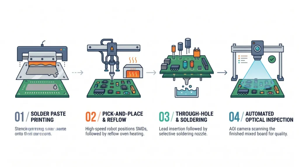
The order can change with board orientation, parts on both sides, heat limits, masking, clearances and available equipment. Selective soldering targets individual areas and may suit a mixed assembly; it is not the only possible route. Altium’s overview of PCB soldering processes describes reflow, wave and selective methods.
Some suitably qualified through-hole parts can be assembled using pin-in-paste reflow. Paste is deposited at the hole openings, the leads are inserted, and the assembly is heated so the solder melts. An IPC-hosted technical paper notes that component dimensions and heat resistance can limit reflow. The process also depends on paste volume, footprint and the assembler’s capabilities. Do not assume every connector can pass through a reflow oven. For the oven stages and profile considerations, see the reflow soldering guide.
Agree on inspection and acceptance requirements with the assembler. The IPC standards overview describes J-STD-001’s soldered-assembly requirements and IPC-A-610’s visual acceptability criteria. Check the customer contract and applicable edition rather than assuming a product class or inspection method.
What affects SMT vs through-hole assembly cost?
The best comparison uses the same board requirements and volume for both options. Costs can include parts, bare-board fabrication, setup, placement or insertion, soldering, inspection, yield and logistics. A through-hole connector can add a process step; an SMT connector can have a different part price or support requirement.
The following figures are invented solely to illustrate the calculation. They are not a supplier quote or company pricing. Assume the fictional controller has one connector per board and both options already use the same SMT line. Hold fabrication, test and yield costs equal even though the connector footprints and drill files differ; exclude all other cost differences.
| Connector option | Added setup | Added part and assembly per board | 100 boards | 1,000 boards |
|---|---|---|---|---|
| SMT | $0 | $0.75 | $75 | $750 |
| Through hole on SMT board | $180 | $0.40 | $220 | $580 |
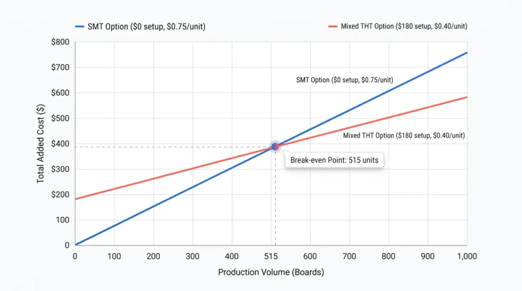
Cost comparison curve showing SMT versus through-hole assembly crossover break-even point at 515 circuit boardsHere the mixed option saves $0.35 per board but adds $180 of setup. The modeled break-even is $180 ÷ $0.35, or about 514.3 boards; at 515 whole boards, the mixed option first has the lower added cost. If the per-board saving disappears, this setup cannot be recovered through that saving.
A real quote may change the result because board area, hole fabrication, sourcing, qualification, fixtures, inspection and yields may differ. Give each supplier the same requirements and quantities. The guide to files needed for a PCBA quote explains which design, parts and test information to prepare.
Surface mount and through-hole FAQs
Can surface-mount and through-hole components go on the same PCB?
Yes. A mixed-technology PCB can combine surface-mount ICs and passives with through-hole connectors or other parts. The assembly route depends on the selected components, board layout and available processes.
Is through-hole always more reliable?
No. Reliability depends on the part, loading, board support, environment, soldering process and qualification. Through-hole leads can help with mechanical retention; a supported surface-mount connector may also meet the requirements. Verify the actual design and test conditions.
Is SMT cheaper for a small run?
Not necessarily. Part prices, labor, setup, equipment already required and the number of boards all matter. Ask for quotes at the quantities you expect; the cost example above is only one invented set of assumptions.
Is SMD the same as SMT?
No. An SMD is a surface-mount device, meaning the component. SMT is the technology used to mount it on surface pads. A board assembled with SMT can also contain through-hole components.
Prepare your assembly request
Share the board files, bill of materials, target quantities, connector load requirements and desired inspection or test scope when requesting PCB assembly services. A project-specific review can compare the parts, layout and process before you commit to either option.