The types of circuit boards used in drones include flight controllers, electronic speed controllers, power distribution boards, sensor and navigation boards, communications boards, and boards for cameras or other payloads. Some drones combine several of these functions on one assembly; others connect separate modules.
Each function places different demands on its printed circuit board (PCB). A flight controller needs clean sensor signals, while a motor controller must handle switching current and heat. Understanding those differences helps a design team decide what to integrate and what to tell its PCB manufacturer.
Key Takeaways
- Flight control, motor drive, power, sensing, communications, and payload control are functions. They do not necessarily require six separate boards.
- A PCB’s function and its construction are different choices: a flight controller, for example, may use a rigid multilayer board, while a camera connection may use flex.
- Set current, thermal, mechanical, signal, and test requirements for each assembly before selecting materials or requesting a quote.
- Inspection of a board or solder joint does not replace functional and environmental testing of the finished aircraft.
In this guide: Board functions | PCB construction | Integrated vs. separate boards | Manufacturing checklist | FAQs
Drone circuit boards at a glance
The table groups drone electronics by job. The actual number of assemblies depends on the aircraft and on how much functionality the design integrates.
| Board or function | Main job | Design concern | Can it be combined? |
|---|---|---|---|
| Flight controller | Reads sensors and issues control commands | Sensor noise, vibration, power integrity | Often integrated with other control or power functions |
| Electronic speed controller (ESC) | Drives an electric motor in response to commands | Current, switching noise, heat | May share an assembly with other ESCs or control electronics |
| Power distribution and monitoring | Routes and monitors electrical power | Current paths, voltage drop, protection | May be part of an ESC or main board |
| Navigation and sensors | Supplies position, motion, altitude, or other measurements | Placement, interference, vibration | Sensors may be onboard or on separate modules |
| Radio and telemetry | Carries control, data, or video signals | Antenna placement, RF layout, interference | Some radios are integrated; others are separate |
| Camera, gimbal, or payload control | Operates mission equipment | Interfaces, space, heat, mechanical movement | Depends on the payload and aircraft |
These are functional categories. Terms such as rigid, flexible, rigid-flex, and high-density interconnect (HDI) describe how a PCB is constructed or routed. A single board can belong to a functional category and have several construction characteristics at once.
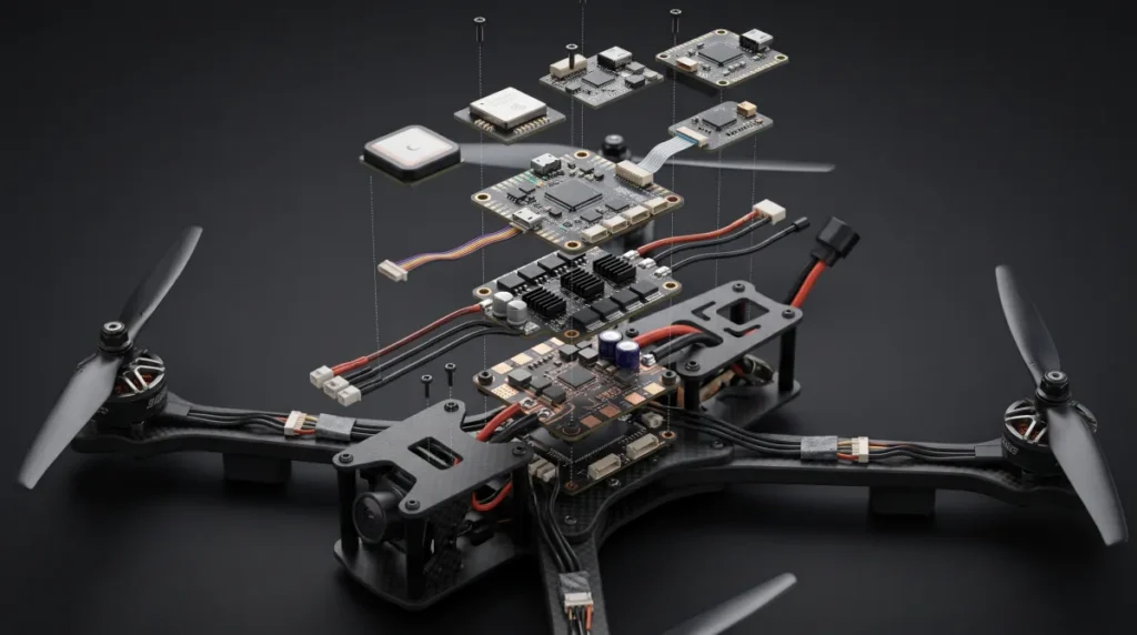
The main types of circuit boards used in drones
Flight controller board
The flight controller is the aircraft’s control hub. It receives measurements such as acceleration and angular rate, processes commands, and sends outputs to actuators. PX4’s flight-controller documentation describes the flight controller as the autopilot hardware on which PX4 firmware runs.
A controller can carry a processor, inertial measurement unit (IMU), power regulation, memory, and connectors for peripherals. Its exact parts and firmware vary by platform. Layout decisions should account for sensor placement, vibration, switching interference, and stable power. Isolating a sensitive sensor mechanically or electrically is a system design task; it cannot be reduced to one PCB material choice.
Electronic speed controller board
An electronic speed controller, or ESC, controls the power delivered to an electric motor in response to a command. In a multirotor, the system needs a motor-control channel for each motor, but several channels may share one physical board.
A concrete example is Texas Instruments’ TIDA-00643 drone ESC reference design, which combines a microcontroller, gate driver, and MOSFETs to drive a brushless motor. Its schematic and layout are specific to that design, not a universal specification.
The ESC has a different layout problem from the flight controller. Its switching devices and current paths create heat and electrical noise. Copper geometry, component placement, the return path, and the way heat leaves the assembly all affect the design. The required copper thickness and trace dimensions depend on current, duty cycle, temperature rise, cooling, and the rest of the stackup; there is no universal drone ESC specification.
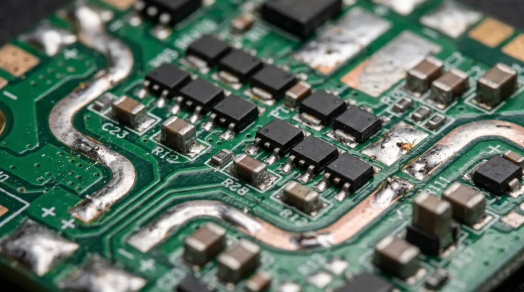
Power distribution and battery-monitoring boards
A power distribution board routes electrical power from the battery to loads such as motor controllers and regulated electronics. A power-monitoring circuit can measure voltage or current and report information to the controller. A battery management system may provide additional battery-specific monitoring or protection, depending on the battery and product architecture. These terms describe related but different functions.
PX4’s power-system documentation describes power modules that supply the controller and monitor battery voltage and current. The distribution path and the controller’s regulated supply must both be considered.
For the PCB, identify normal and peak loads, connectors, protection needs, voltage drop, and the heat created along the power path. A compact board may combine distribution with ESCs or flight control. That can reduce the number of interconnects, but it also places power circuitry closer to sensitive electronics.
Navigation and sensor boards
Sensors give the aircraft information about its motion and surroundings. An IMU commonly provides acceleration and angular-rate measurements. Other sensors may provide altitude or heading information. A global navigation satellite system (GNSS) receiver can provide position and timing information when the system has a usable satellite signal.
Some sensors sit on the flight-controller assembly; others are placed on separate modules. Location matters: a sensor can be affected by vibration, heat, electrical noise, nearby metal, or the physical environment it is meant to measure. For an external GNSS and compass module, PX4’s mounting guidance recommends placing it as far as practical from motor and ESC power wiring. A separate sensor board can make placement more flexible, while introducing connectors and cable-routing decisions.
Radio, telemetry, and video boards
Communications electronics carry information between the aircraft and other equipment. Depending on the drone, links may handle operator commands, telemetry, video, or several of those functions. A GNSS receiver is also radio-based, but its job is receiving satellite navigation signals, not transmitting the pilot’s commands.
PX4’s telemetry documentation describes links between a vehicle and ground-control software; the supported equipment and interfaces vary by system.
RF performance depends on the complete assembly, including the antenna, its placement, the enclosure, nearby conductors, and the PCB layout. Identify the frequency, interface, antenna arrangement, and impedance requirements before choosing a stackup. A specialized laminate can be useful for some designs, but a radio function alone does not establish that it is required.
Camera, gimbal, companion-computer, and payload boards
A camera or gimbal board supports imaging or stabilization; another payload board may control a sensor or mission-specific device. Some aircraft also carry a companion computer for processing tasks that are separate from the flight controller. These boards are optional and depend on the aircraft’s purpose.
A moving gimbal creates mechanical and interconnect constraints that a fixed controller may not have. Flex circuits can help connect moving or tightly packaged parts, provided the bend geometry, reinforcement, and expected movement are designed for the application. See the flex PCB guide for construction details.
Which PCB construction fits each drone board?
Choose the construction after defining the board’s function, electrical demands, packaging, and environment. The following are starting points for discussion, not prescribed pairings.
| PCB construction | Where it may fit | Potential benefit | Trade-off to check |
|---|---|---|---|
| Rigid FR-4 multilayer | Flight control, power, and other fixed assemblies | Supports components and routing in a familiar construction | Stackup, copper, and mechanical mounting still need design review |
| Flexible PCB | Camera or sensor interconnects | Can route through compact or moving spaces | Bend region, reinforcement, and movement life need attention |
| Rigid-flex PCB | An assembly needing rigid component areas joined by flex | Can integrate rigid and flexible regions | Stackup, fabrication, and bend requirements need early review |
| HDI features | Dense controllers or compact modules | Fine features and microvias can help route dense packages | Adds fabrication and inspection constraints |
| Specialized RF or thermal construction | A radio or power assembly with demonstrated material needs | Can address a specific electrical or thermal requirement | Cost, fabrication options, and actual benefit depend on the design |
For flexible connections, distinguish a circuit bent during installation from one that moves repeatedly in use. Altium’s discussion of static and dynamic flex explains how repeated bending places different demands on the conductors and stackup.
For example, a flight controller can be both rigid and HDI. An ESC is not automatically a metal-core board, and a radio board does not automatically need a high-frequency laminate. Discuss the load, loss, space, and reliability requirements with the fabricator before fixing the stackup. Explore rigid-flex PCB manufacturing or HDI PCB manufacturing when those features fit the design.
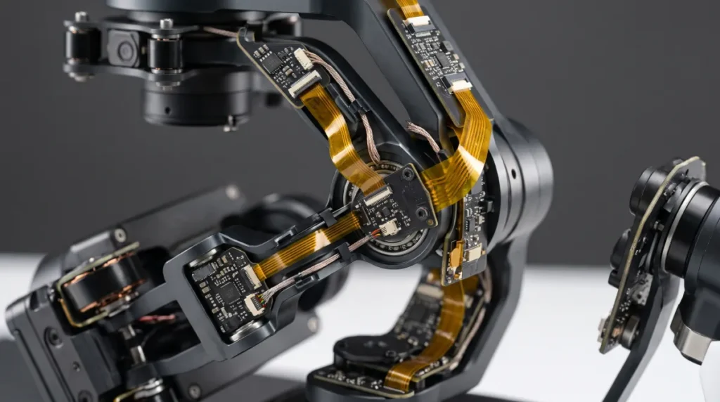
Integrated drone boards vs. separate modules
Integration changes interfaces and serviceability as well as board layout. Consider two illustrative architectures; neither is a measured design or a recommendation for every drone.
Example A: compact integrated assembly. A small aircraft combines its flight controller and several ESC channels on one board. Fewer board-to-board connections can simplify packaging. The team must also manage heat and switching noise near the processor and sensors. A fault in one section may require replacing the combined assembly.
Example B: separate control and power assemblies. Another aircraft places the flight controller, ESCs, power distribution, and payload electronics on separate boards. The team can position and replace modules individually, but must design and secure more interconnects. Each cable and connector needs a defined electrical and mechanical interface.
| Decision | Integrated assembly | Separate modules |
|---|---|---|
| Packaging | Fewer separate assemblies; denser layout | More placement flexibility; more interconnects |
| Electrical and thermal design | Sensitive and high-power circuits may be close together | Physical separation is possible, but cables can introduce new concerns |
| Repair or replacement | A shared board may be replaced as a unit | An individual module may be replaceable |
| Verification | Test interactions on the combined board | Test each module and its interfaces as a system |
Neither approach is automatically lighter, cheaper, or more reliable. Compare complete assemblies, including connectors, wiring, enclosures, cooling, maintenance, and test effort.
How to choose and manufacture a drone PCB
A useful manufacturing request describes the requirements of the specific board rather than asking for a generic drone PCB. Prepare the following with the design team and supplier:
- Function and environment. Identify the assembly’s role, mounting, expected vibration, temperature exposure, and available space.
- Electrical loads. Provide operating and peak voltage and current, expected duty cycle, sensitive signals, and any RF or controlled-impedance requirements.
- PCB design. Supply fabrication files, stackup requirements, copper specifications, dimensions, finish, and any flex or mechanical constraints. Ask for design-for-manufacturing review where details are unresolved.
- Assembly information. Provide the bill of materials, approved part numbers and substitutions, placement data, assembly drawings, polarity, and programming requirements where relevant.
- Inspection and test. Agree on the checks, fixtures, procedures, acceptance criteria, and documentation needed for the project. Separate PCB and assembly inspection from testing the complete aircraft.
A PCB manufacturing supplier can review the bare-board requirements, while PCB assembly services can address component placement and assembly checks. Confirm the proposed process and its suitability for the particular design before ordering.
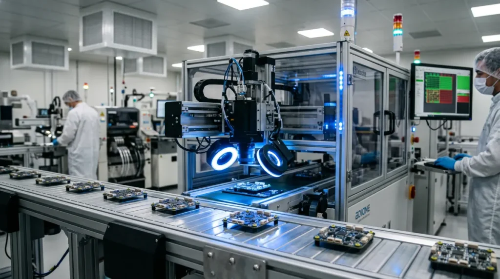
Common drone PCB design and assembly mistakes
- Sizing power paths without the operating conditions. Provide current, duration, temperature limits, copper geometry, and cooling assumptions rather than relying on a generic trace-width rule.
- Ignoring sensor and power interactions. Review component placement, return paths, power regulation, and mechanical mounting together so noisy loads do not undermine sensitive measurements.
- Treating the connector as an afterthought. Check orientation, retention, cable movement, assembly access, and the loads transferred to the board.
- Confusing inspection with qualification. Inspection can find manufacturing defects; it cannot by itself establish that an aircraft meets its functional, environmental, or regulatory requirements. Define the necessary system tests and their acceptance criteria for the intended use.
Frequently asked questions
How many circuit boards does a drone have?
There is no fixed number. A compact drone can combine flight control, motor control, and power functions on a shared assembly, while another design uses separate modules. Camera, radio, navigation, and payload arrangements also vary with the aircraft.
Are a flight controller and an ESC the same board?
They perform different jobs. A flight controller processes measurements and commands to control the aircraft; an ESC drives a motor. They can be separate boards or integrated into one physical assembly.
Do drones use flexible PCBs?
Some do. Flexible PCBs can connect components in confined spaces or moving assemblies, such as a camera mechanism. Suitability depends on the bend geometry, movement, materials, and expected service conditions. A flex circuit is not necessary for every drone.
Plan the board around its job
Start with the aircraft’s functions, then decide how to divide them among assemblies. Define the electrical, thermal, mechanical, and test requirements for each board before selecting its construction. That gives the manufacturer enough context to review the design and helps the product team compare integration choices on the full system, not PCB area alone.