What is Copper Clad Laminate (CCL)?
At its core, Copper Clad Laminate (CCL) is the foundational composite material used to construct printed circuit boards (PCBs). It is created by taking a reinforcing substrate—most commonly woven fiberglass fabric or cellulose paper—impregnating it with a high-performance insulating resin, and cladding it on one or both sides with a micro-thin layer of high-purity copper foil under intense heat and pressure.
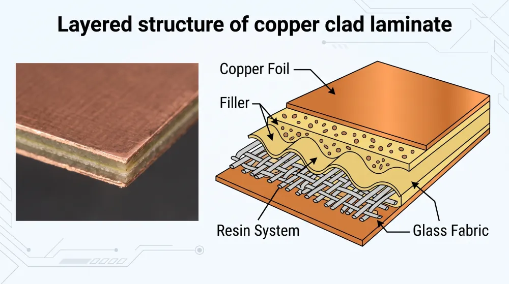
As illustrated above, a standard CCL relies on three primary building blocks to achieve structural and electrical integrity:
- Copper Foil: The top and bottom conductive layers that will eventually be etched to form physical electrical pathways.
- Resin System & Filler: Formulated to dictate thermal resistance, flame retardancy, and dielectric qualities.
- Glass Fabric or Reinforcing Substrate: The physical “backbone” that determines mechanical strength, thickness uniformity, and overall dimensional stability.
The Crucial Role of CCL in PCB Manufacturing
In modern electronics, a PCB is only as reliable as the raw substrate from which it is made. Copper Clad Laminate acts as both the physical skeleton and the electrical nervous system of virtually every electronic device.
Without high-quality CCL, modern advancements in high-frequency communications, aerospace electronics, and consumer hardware would not be possible. It fulfills three critical functions in PCB fabrication:
- Electrical Interconnection: The laminated copper foil serves as the raw material for subtractive etching. Chemical processes remove unwanted copper to leave behind highly precise conductive traces, pads, and vias that connect components.
- Structural and Mechanical Support: It provides the rigid or flexible physical platform required to mount, solder, and hold heavy components securely under environmental vibration and mechanical stress.
- Insulation and Signal Integrity: The cured resin-impregnated substrate acts as a robust dielectric barrier. This prevents electrical leakage between adjacent conductive layers, ensuring signals travel cleanly along their intended pathways without interference.
The Material Structure of Copper Clad Laminate
Understanding what goes into a copper clad laminate (CCL) is essential for grasping how it performs under stress. At its core, a CCL is a sandwich of copper foil, reinforcing fabric, and resin.
Substrate and Prepreg Options (FR4 and Beyond)
The backbone of any CCL is its reinforcing matrix, typically made of fiberglass woven cloth impregnated with resin (known as prepreg).
- FR4 (Flame Retardant 4): This is the industry workhorse. Utilizing an epoxy resin matrix, FR4 offers an excellent balance of cost, mechanical strength, and electrical insulation. For a deeper dive into how these mechanical and thermal limits behave, you can explore our detailed guide on FR-4 material properties.
- High-Frequency and High-Speed Substrates: When standard FR4 cannot handle high-frequency signals, we turn to advanced materials like PTFE (Teflon), polyimide, or polyphenylene ether (PPE) to minimize signal loss.
| Material Type | Common Resin | Key Advantage | Best Used For |
|---|---|---|---|
| Standard FR4 | Epoxy | Cost-effective, strong | General electronics, consumer tech |
| High-Tg FR4 | Modified Epoxy | Superior thermal resistance | Multilayer PCBs, industrial power |
| PTFE | Fluoropolymer | Extremely low signal loss | RF, microwave, and radar systems |
| Polyimide | Polyimide | Excellent flexibility & thermal stability | Flex and rigid-flex applications |
Copper Foil Characteristics
The conductive outer layer of a copper clad laminate consists of high-purity copper foil. The choice of copper directly influences signal integrity and peel strength:
- Electrodeposited (ED) Copper: Created via electrolysis, this copper has a rougher profile, which provides excellent mechanical adhesion to the resin.
- Rolled Annealed (RA) Copper: Created by mechanically rolling copper ingots. It is much smoother and highly flexible, making it the premier choice for flexible circuits.
- Foil Thickness: Measured in ounces (oz). Standard boards typically use 1 oz (35 µm) or 0.5 oz (18 µm) copper, while high-power applications require heavy copper to manage high current loads.
Electrical Integration and Performance Profiles
The synergy between the copper foil and the dielectric substrate dictates how the circuit performs under real-world operating conditions:
- Dielectric Constant ($D_k$): Determines signal propagation speed. Lower, stable $D_k$ values are critical for high-speed digital designs.
- Dissipation Factor ($D_f$): Represents signal energy lost as heat. High-frequency boards require materials with ultra-low $D_f$ to prevent signal degradation.
- Coefficient of Thermal Expansion (CTE): Matching the expansion rate of the copper and the substrate prevents delamination, pad lifting, and joint failures during thermal cycling.
How Copper Clad Laminates Are Classified
Selecting the right copper clad laminate (CCL) requires understanding how these materials are categorized. Manufacturers classify them based on three primary factors: the reinforcing material, the resin binder, and the physical rigidity of the finished board.
Classification by Reinforcing Material
The reinforcement base forms the physical backbone of the copper clad laminate, determining its structural integrity and heat resistance.
- Glass Fiber Cloth (FR-4): The industry standard. It uses woven fiberglass impregnated with epoxy resin, offering excellent mechanical strength and electrical properties.
- Paper Base (FR-1, FR-2): Made from cellulose paper saturated with phenolic resin. It is highly cost-effective but restricted to simple, single-sided consumer electronics due to lower physical durability.
- Composite Base (CEM-1, CEM-3): A hybrid option. CEM-1 features a paper core with glass cloth surfaces, while CEM-3 uses non-woven glass core with woven glass surfaces. These act as mid-tier alternatives to pure FR-4.
Classification by Resin Type
The resin system binds the reinforcement fibers together and dictates the thermal, chemical, and electrical performance limits of the board.
| Resin Type | Key Characteristics | Typical Applications |
|---|---|---|
| Epoxy Resin | Excellent adhesion, electrical insulation, and moisture resistance. | Standard consumer electronics, automotive parts |
| Phenolic Resin | Flame retardant and highly economical, but lower thermal tolerance. | Power supplies, simple home appliances |
| Polyimide (PI) | Extreme thermal stability and reliability in harsh environments. | Aerospace, military, and high-temperature industrial tools |
Classification by Mechanical Rigidity
How much a board needs to bend during installation or operation determines its rigidity classification.
- Rigid CCL: The most common type. It provides a solid, unbending platform for heavy components and multi-layer stackups.
- Flexible CCL (FCCL): Built using thin plastic films (typically polyimide or polyester). These can bend, fold, or twist, making them ideal for ultra-thin wearables and tight enclosures.
- Rigid-Flex CCL: A hybrid material integration that combines rigid sections for component mounting with flexible sections for dynamic bending.
Carefully evaluating these classifications is a critical step when finalizing your BOM for PCB assembly, as the choice of laminate directly impacts both the manufacturing yield and the long-term reliability of your product.
The Manufacturing Process of CCL
Producing high-quality copper clad laminate requires absolute precision at every stage. Because the laminate serves as the structural and electrical foundation of the circuit board, even a microscopic defect during fabrication can compromise the performance of the final electronics. We break the core production process down into three essential phases.
Raw Material Preparation and Treating
The process begins with the preparation of the reinforcement material—typically high-purity woven fiberglass cloth.
- Resin Impregnation: We pass the fiberglass fabric through a treating machine containing a formulated liquid epoxy resin bath.
- Precise Coating: The fabric is thoroughly saturated to ensure an even distribution of the resin matrix.
- B-Stage Curing: The wet sheet enters a high-temperature drying oven to evaporate solvents and partially cure the resin. This semi-cured material is cut into sheets known as prepreg.
Lamination and Pressing
Once the prepreg sheets are prepared, they are assembled with high-purity copper foils in a cleanroom environment to prevent dust contamination.
- The Stack-up: We layer the prepreg sheets together to achieve the target thickness, placing the copper foil on one or both outer sides.
- Vacuum Hot Pressing: The stacked layers are loaded into a heavy-duty vacuum press. Under intense heat and high pressure, the semi-cured resin liquefies, flows into the copper micro-topography, and completely cures (C-stage polymerization).
- The Result: A perfectly unified, rigid sheet of copper clad laminate. This robust construction ensures the material can withstand the intense heat of the modern printed circuit board assembly process without warping or delaminating.
Quality Control and Common Standards
To ensure every batch of copper clad laminate meets global manufacturing requirements, we implement strict quality assurance protocols at the end of the line:
- Peel Strength Testing: We measure the force required to peel the copper foil from the substrate to ensure it won’t lift during soldering.
- Dimensional Stability: Verifying that the laminate maintains its exact physical size under varying thermal stresses.
- IPC-4101 Compliance: Every sheet is tested against standard IPC-4101 specifications for base materials, ensuring proper dielectric breakdown voltage, glass transition temperature ($T_g$), and flame-retardant performance.
Key Performance Characteristics of High-Quality CCL
Selecting the right copper clad laminate directly determines how well your printed circuit board performs under real-world stress. High-quality laminates must strike a balance between thermal survival, electrical precision, and structural endurance.
Thermal Conductivity and Heat Resistance
Modern electronics pack more power into smaller spaces, making thermal management a critical priority. High-quality copper clad laminate must withstand intense operating temperatures without delaminating or losing structural integrity.
- Glass Transition Temperature (Tg): This is the point where the base resin shifts from a rigid state to a softened, rubbery state. For highly demanding thermal environments, using a specialized high Tg PCB substrate ensures the board maintains its shape and electrical properties.
- Decomposition Temperature (Td): The threshold where the organic resin chemically breaks down. High-quality laminates maintain high Td values to survive lead-free soldering processes.
- Thermal Conductivity: Effective heat dissipation prevents localized hot spots, extending the overall lifespan of the active components on your board.
Dielectric Performance and Electrical Insulation
For high-speed and high-frequency applications, the electrical properties of the resin matrix are just as important as the copper itself. Standard materials, like those explored in our comprehensive FR4 PCB guide, provide excellent everyday insulation, but specialized high-frequency systems demand optimized electrical profiles.
- Dielectric Constant (Dk): A low and stable Dk is vital for maintaining signal integrity and fast propagation speeds across high-frequency transmission lines.
- Dissipation Factor (Df): Also known as the loss tangent, a lower Df minimizes signal attenuation (strength loss), ensuring clean data transmission.
- Volume and Surface Resistivity: High insulation resistance prevents electrical leakage between closely spaced trace lines, even under high humidity.
Mechanical Strength and Dimensional Stability
A circuit board must survive assembly forces, mechanical vibration, and thermal expansion cycles without cracking or warping.
| Performance Metric | What It Measures | Why It Matters for Your PCB |
|---|---|---|
| Coefficient of Thermal Expansion (CTE) | The rate at which the material expands when heated. | A low Z-axis CTE protects delicate copper-plated through-holes (PTHs) from cracking during thermal cycling. |
| Dimensional Stability | The material’s ability to return to or maintain its original dimensions. | Prevents layer shifting and misalignment during high-pressure multi-layer lamination. |
| Peel Strength | The bond strength between the copper foil and the underlying substrate. | High peel strength prevents traces from lifting off the board during soldering or rework. |
How to Choose the Right Copper Clad Laminate for Your PCB
Selecting the correct copper clad laminate (CCL) is one of the most critical decisions in the board design process. The laminate you choose dictates how your board handles heat, high-frequency signals, and physical stress.
Matching CCL Material to Application Requirements
Different applications demand specific material properties. To make sure your design functions reliably in the field, we recommend matching your product type to these standard material classes:
- Standard Consumer Electronics: Standard FR4 is the go-to choice for toys, basic home appliances, and low-frequency devices.
- High-Frequency & RF Applications: Requires materials with a low dielectric constant ($D_k$) and low loss tangent ($D_f$), such as PTFE-based laminates, to maintain signal integrity.
- High-Power & Automotive Systems: Demands high thermal conductivity and a high glass transition temperature (Tg) to withstand constant heat dissipation.
When you prepare your fabrication files, keeping a strict PCB DFM checklist ensures that your chosen copper clad laminate thickness and copper weight are fully compatible with your manufacturer’s production limits.
Evaluating Cost versus Performance
Over-specifying your laminate drives up production costs unnecessarily, while under-specifying leads to board failures. We use this straightforward matrix to balance performance requirements against your budget:
| Material Type | Relative Cost | Key Strength | Best Use Case |
|---|---|---|---|
| Standard FR4 | Low | Balanced mechanical properties | General consumer goods |
| High-Tg FR4 | Medium | Superior heat resistance | Industrial controls, automotive |
| Halogen-Free | Medium-High | Environmentally friendly | Green electronics, strict compliance |
| PTFE / Rogers | High | Ultra-low signal loss | 5G, radar, high-frequency RF |
If you are currently vetting vendors to secure these specialized materials at competitive rates, utilizing a structured PCB supplier qualification checklist helps ensure your partner can consistently source high-quality, genuine laminates.
Future Trends and New Technology in CCL Materials
The electronics industry is moving toward higher speeds, smaller footprints, and greener footprints. These shifts are directly shaping the next generation of copper clad laminate technology:
- Ultra-Low Loss Materials for 5G/6G: Traditional FR4 cannot support high-frequency millimeter waves. Manufacturers are developing extremely low-loss hydrocarbon and PTFE laminates to prevent signal degradation.
- Thinner Profiles for HDI: High-density interconnect (HDI) designs require ultra-thin CCLs to support microvias and multi-layer stacking without bulk.
- Eco-Friendly and Biodegradable Resins: There is an industry-wide push toward halogen-free formulations and recyclable resin matrices to reduce e-waste and meet evolving global environmental regulations.
