Electronic Circuit

Here, you can acquire professional knowledge covering the entire chain from PCB design to assembly, as well as precise analysis of the latest trends in the electronics industry.

What Is a Through Hole? PCB Types, Uses, and Design Guide

A through hole is an opening that passes completely from one side of a printed circuit board (PCB) to the other. It may be plated with conductive copper to create an electrical connection, or left unplated for mechanical use. Through holes are commonly used for component leads, connectors, vias, mounting hardware, alignment pins, and slots.…

Cross-section diagram of a plated through hole (PTH) in a multilayer PCB showing copper barrel and annular ring

LED Anode and Cathode: How to Identify Positive and Negative Terminals

An LED (Light Emitting Diode) is a polarized semiconductor device that allows current to flow in only one direction. To illuminate an LED, you must connect its positive and negative terminals correctly within your circuit. On standard through-hole LEDs, the longer leg and the rounded side represent the anode, while the shorter leg and the…

through hole led

What Is GND in Electronics? Ground Meaning, Symbols & Types Explained

In an electronic circuit, GND stands for Ground, which is defined as the designated reference point used for measuring voltages and the common return path for electrical currents. While it is standard practice to label this node as 0 V, GND does not automatically mean physical earth ground, a protection earth connection, or even a…

voltage ground reference diagram 1

0402 Resistors Guide: Size, Specs, and Selection

Hardware design always comes down to a battle for board space. As consumer wearables, IoT devices, and high-performance computing modules pack more features into smaller enclosures, printed circuit board (PCB) real estate has become an incredibly valuable commodity. Moving away from legacy through-hole parts and bulkier surface-mount devices (SMDs) is no longer optional—it is a…

IPC-TM-650 Explained: PCB Test Methods, Key Procedures, and Quality Uses

“Test to IPC” is not a complete PCB requirement. A supplier still needs the method, revision, samples, conditions, and acceptance criteria before it can quote or run the work. IPC-TM-650 is the procedure side of PCB testing. It helps engineers choose a way to measure a board characteristic. The governing specification, drawing, or contract still…

what is ipc tm 650

FR-4 Material Properties for PCB Design

FR-4 is the default laminate for many rigid printed circuit boards, but it is not a single fixed material. Its dielectric constant, thermal conductivity, Tg, CTE, CTI, and loss behavior depend on the laminate grade, resin system, glass weave, copper construction, supplier, and test method. For PCB engineers, the useful question is not whether FR-4…

PCB Via Guide: Types, Design Rules, and Selection Tips

A PCB via is a plated interconnect that lets signals, power, ground, or heat move between copper layers in a printed circuit board. Via choice affects routing density, fabrication cost, assembly yield, signal integrity, and thermal performance, so it should be part of stackup and DFM planning, not a cleanup step at the end. For…

pcv via guide

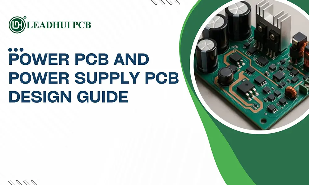
Power PCB and Power Supply PCB Design Guide

A power PCB is the circuit board that receives, converts, regulates, distributes, or monitors electrical power. A power supply PCB is a more specific type of power PCB that converts an input source—such as AC mains, a battery, USB power, or a DC bus—into stable output voltage rails for an electronic product. The quality of…
power supply pcb design guide

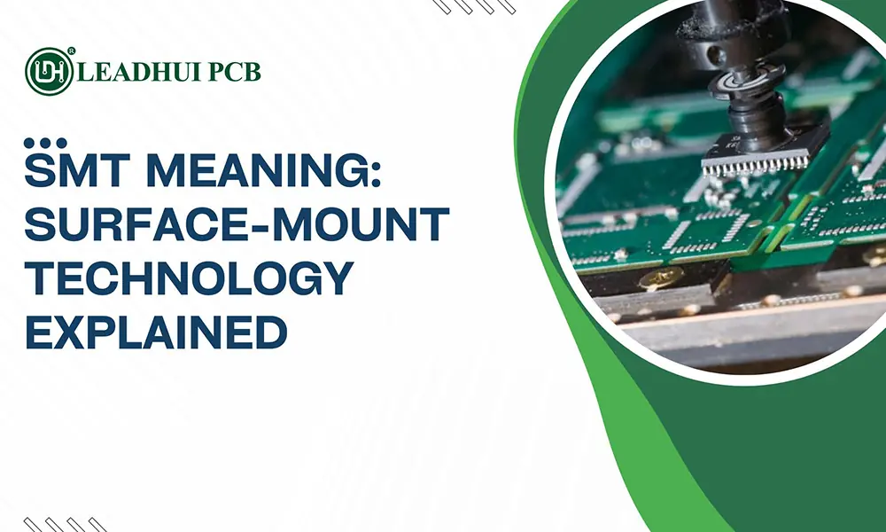
SMT Meaning: Surface-Mount Technology Explained

SMT means Surface-Mount Technology: a method of attaching electronic components directly onto the surface of a printed circuit board (PCB). Rather than inserting long component leads through drilled holes, SMT uses small surface-mount components that are placed on solder-coated pads and permanently connected through controlled heating. In practical terms, SMT is what makes modern electronics…
smt meaning

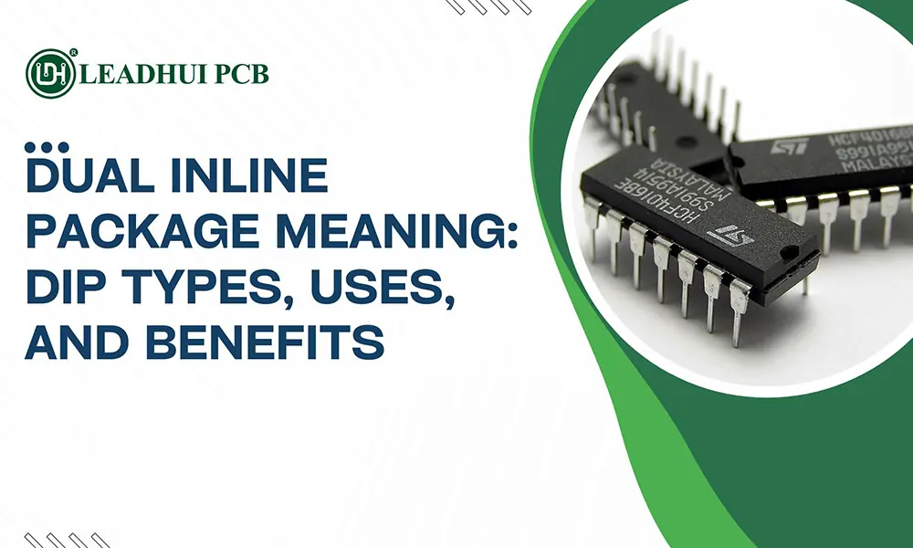
Dual Inline Package Meaning: DIP Types, Uses, and Benefits

A dual inline package, usually abbreviated as DIP or DIL, is an electronic-component package with a rectangular body and two parallel rows of pins. Those pins pass through holes in a printed circuit board (PCB) or plug into a socket, creating a simple, durable, and easy-to-handle connection. The dual inline package meaning is therefore more…
dual inline package meaning